Solenoid Bit Reader
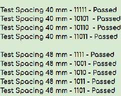
Macro-scale hard-disk-reader analog decoding falling magnetic bits at 100% accuracy.
- Year
- 2026
- Category
- hardware
- Built at
- Physics 4BL
- Team
- 2 people
Stack
- Problem
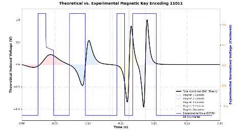
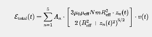
- Faraday induction gives you a voltage proportional to the rate of change of flux, so a falling magnet produces a brief spike rather than a level.
- Approach
- Presence-based encoding over polarity-based.
- Result
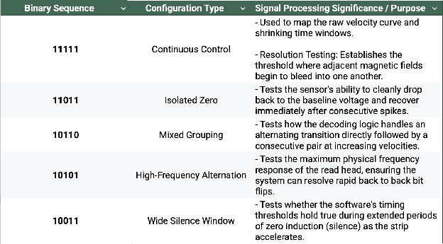
- Four binary sequences decoded at 100% accuracy.
How it works
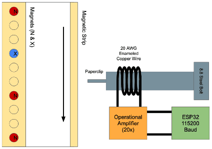
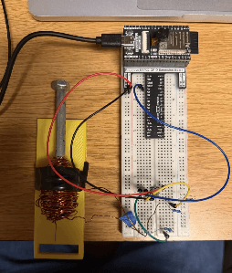
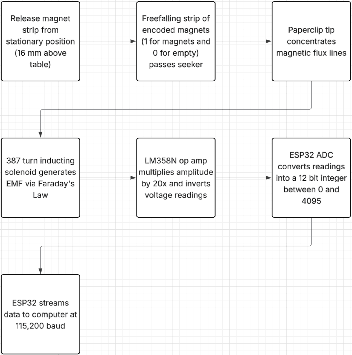
A hard drive reads data by sensing the magnetic field of bits passing a coil. This is that mechanism rebuilt at a scale you can watch: magnets fall past a hand-wound solenoid under gravity, and the induced voltage spike is decoded back into the binary sequence they encode.
The problem
Faraday induction gives you a voltage proportional to the rate of change of flux, so a falling magnet produces a brief spike rather than a level. Two constraints shaped the design:
- The ESP32's ADC only reads 0-3.3V, and the raw coil output was far below that. An LM358N operational amplifier stage provides 20x gain to bring spikes into readable range.
- Gravity means the bits do not arrive at a constant rate. Each successive magnet is moving faster than the last, so the time window for a bit shrinks continuously down the drop.
Design decisions
Presence-based encoding over polarity-based. With a unipolar ADC, encoding a 1 as north-up and a 0 as south-up would put half the signal below the readable floor. Encoding instead as magnet-present versus empty-slot keeps every symbol inside the window, at the cost of needing a clock to know when an empty slot went by.
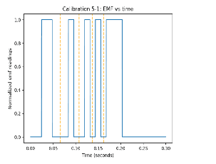
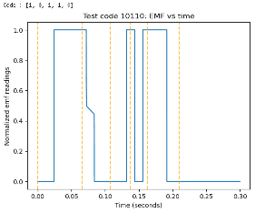
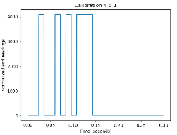
A start bit for clock synchronization. Since empty slots produce no signal, the decoder cannot count them directly. A known start bit establishes t=0, and a calibration matrix built across three intervals maps the shrinking windows that follow.
What did not work
Initially, reading voltage changes from the solenoid were too low, meaning the ESP-32 used in the project was unable to read and understand when a bit passed the sensor. The ESP-32 also was unable to read voltage changes fast enough, meaning measures had to be taken to ensure bits were not dropped, such as increasing the distance between bits.
Results
Four binary sequences decoded at 100% accuracy. The calibration work established a 40 mm resolution limit — closer than that and adjacent spikes merge at the velocities reached toward the end of the drop.
Figures